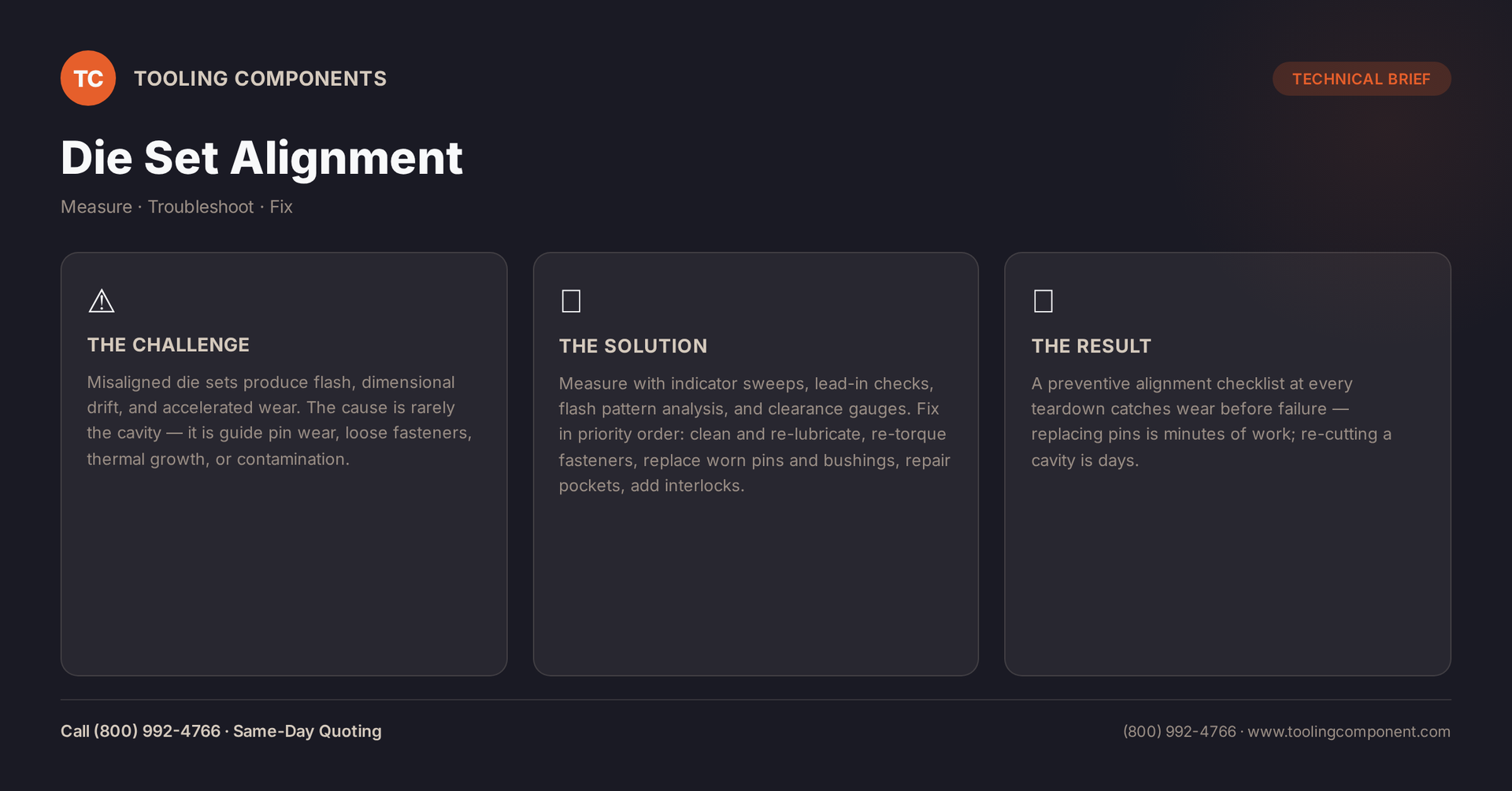
Die Set Alignment
Measure · Troubleshoot · Fix
Die Set Alignment: Measuring, Troubleshooting, and Fixing Misalignment
A die set is only as good as its alignment. The guide pins, bushings, and interlocks that keep mold halves closing true are the difference between clean parts and flash, wall-thickness variation, and accelerated tool wear. When parts start showing signs of misalignment, the fix is rarely a new cavity — it's a measurement, a diagnosis, and a targeted repair.
This guide walks through the common causes of die set misalignment, how to measure it, and what to fix first.
Common Causes of Die Set Misalignment
| Cause | Symptom | Why It Happens |
|---|---|---|
| Guide pin / bushing wear | Part-to-part dimension drift, flash on one side | Lubrication failure, contamination, or simply cycle count — pins and bushings wear and the clearance grows unevenly |
| Bushing bore wear in the die shoe | Consistent shift in one direction | Press fits loosen under cyclic load; the bushing moves in its pocket instead of guiding the pin |
| Thermal growth | Misalignment appears after warm-up, disappears when cold | Mold halves heat at different rates; guide system must accommodate differential expansion |
| Loose die shoe fasteners | Intermittent flash, movement between shots | Grade 12.9 socket head cap screws backing out under vibration — the die set shifts on its shoes |
| Contamination on guide surfaces | Sticking, erratic closing, galling | Flash, fines, or dried lubricant built up on pin and bushing surfaces |
How to Measure Die Set Alignment
- Indicator sweep on the guide pins. Mount a dial indicator on the ejector half and sweep the pin at two heights. More than 0.001" difference between readings indicates pin deflection or bushing wear.
- Lead-in check. With the mold open, observe the pins entering the bushings at the slowest closing speed. Any side loading or scrubbing on entry is a red flag.
- Part dimension trend. Measure critical part dimensions every 50–100 cycles. A steady drift in one direction is alignment wear; random variation is more likely a process or material issue.
- Flash pattern analysis. Flash on the same side, shot after shot, points to a fixed geometric error in the die set. Flash that moves around points to contamination or loose fasteners.
- Clearance measurement. With the mold closed and lightly clamped, measure pin-to-bushing clearance with feeler gauges. Compare to the design spec — typically 0.0005"–0.0015" per side for plain bearing sets.
What to Fix First
| Priority | Fix | When |
|---|---|---|
| 1 | Clean and re-lubricate guide pins and bushings | Always — cheapest fix, resolves contamination issues immediately |
| 2 | Re-torque die shoe fasteners to spec | If loose fasteners are suspected; check the cross pattern and use a calibrated wrench |
| 3 | Replace worn guide pins and bushings | When clearance exceeds design spec or wear is visible |
| 4 | Rebore or replace worn bushing pockets | When the bushing bore in the die shoe has opened up — a machine shop repair |
| 5 | Add interlocks (side locks) | When lateral loads are flexing the guide pins — shift load to positive interlocks |
Preventive Alignment Checklist
- [ ] Verify guide pin and bushing clearance at every mold teardown
- [ ] Re-torque die shoe fasteners to spec after the first 100 cycles of a new setup
- [ ] Log indicator readings over time to track wear rate — replacement before failure, not after
- [ ] Keep guide surfaces clean; use the correct lubricant for the operating temperature
- [ ] Inspect interlocks and side locks for wear on their mating faces
- [ ] Replace grade 12.9 fasteners at the first sign of necking or thread distortion
Need replacement guide pins, bushings, interlocks, or grade 12.9 fasteners? Tooling Components stocks the full range — call 814-438-7657 or email sales@toolingcomponent.com. Same-day quoting on mold and die components since 1987.