En el moldeo por inyección, el enfriamiento suele representar entre el 60% y el 80% del tiempo total del ciclo. Cada grado de enfriamiento desigual introduce deformaciones, marcas de hundimiento y variaciones dimensionales. Sin embargo, muchos diseños de moldes consideran la colocación del canal de enfriamiento como una idea de último momento: un patrón de orificios perforados rectos que pueden corresponder o no al perfil térmico de la pieza.
Termodinámica del enfriamiento de moldes
La transferencia de calor en un molde de inyección sigue una física predecible. El polímero fundido (normalmente entre 400 y 550 °F para los termoplásticos de ingeniería) debe liberar suficiente energía térmica para alcanzar la temperatura de expulsión (normalmente entre 140 y 200 °F) antes de que se abra el molde. La proximidad del canal de enfriamiento a la superficie de la cavidad (medida como la distancia desde la línea central del canal hasta la pared de la cavidad) determina la tasa de extracción de calor. Como regla general: la distancia entre el canal y la cavidad debe ser de 1,5 a 2 veces el diámetro del canal. A mayores distancias, el tiempo de enfriamiento aumenta exponencialmente.
Configuraciones del canal de enfriamiento
Varios diseños de canales de enfriamiento abordan desafíos específicos del molde. Circuitos en serie: diseño más simple, pero la temperatura aumenta progresivamente en todo el circuito, creando un enfriamiento desigual. Circuitos paralelos: proporcionan una temperatura uniforme si cada rama tiene la misma resistencia al flujo, pero las caídas de presión deben equilibrarse cuidadosamente. Deflectores en espiral/canal: excelentes para enfriar el núcleo en cavidades cilíndricas, forzando al refrigerante a lo largo de una trayectoria helicoidal. Burbujeadores/fuentes: ideales para pasadores de núcleo profundos y cavidades ciegas donde los canales convencionales no pueden llegar. Enfriamiento conformado: el estándar emergente que utiliza la fabricación aditiva para crear canales de enfriamiento que siguen el contorno exacto de la superficie de la cavidad.
Enfriamiento conforme: el estándar de rendimiento
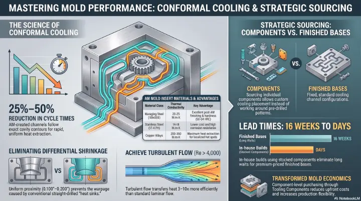
Los insertos de molde fabricados aditivamente con canales de enfriamiento conformes están transformando las herramientas de alta producción. A diferencia de los canales perforados rectos que pueden pasar 0,500 pulgadas desde la superficie de la cavidad en algunas áreas y 1,500 pulgadas en otras, los canales conformes mantienen una proximidad constante de 0,100 a 0,150 pulgadas en toda la cavidad. Esto reduce el tiempo total del ciclo entre un 25 % y un 50 % y prácticamente elimina la deformación relacionada con el enfriamiento.
Uso de herramientas de análisis de refrigeración
Antes de cortar acero, utilice un software de simulación de llenado de moldes (Moldex3D, Autodesk Moldflow) para: identificar los puntos calientes donde debe aumentar la densidad del canal de enfriamiento; visualizar la distribución del flujo de refrigerante en circuitos paralelos; y predecir la temperatura de la pieza en el momento de la expulsión. Muchos problemas de enfriamiento que aparecen durante las pruebas de moldes (marcas de hundimiento, deformación excesiva, ciclos largos) eran predecibles durante la fase de diseño con un análisis adecuado.
Tooling Components suministra componentes de enfriamiento de moldes, incluidos burbujeadores, deflectores, pasadores térmicos e inserciones de enfriamiento conformado. Póngase en contacto con nuestro equipo para obtener asistencia en el diseño del sistema de refrigeración.