Side Locks and Locating Rings: A Selection Guide for Mold Alignment
Side locks and locating rings are the alignment components that ensure your mold halves close precisely every cycle. Get them wrong and you get flash, wall thickness variation, and accelerated wear on leader pins. This guide covers the types, sizing, and selection criteria for both components.
Side Locks (Interlocks)
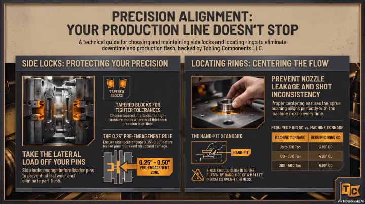
Side locks, also called interlocks or cam locks, provide positive alignment between the two mold halves. They engage before the leader pins and take the lateral load off the pins, extending pin life and improving part quality.
Types of Side Locks
- Angle Pin Interlocks: The most common type. A male angle pin on one half engages a female bushing on the other. Available in straight or tapered versions. Load capacity depends on pin diameter and angle.
- Tapered Interlocks: Male-female tapered blocks that lock with a wedging action. Higher lateral load capacity than angle pins. Used in large molds or when wall thickness precision is critical.
- Rectangular Interlocks: Flat-sided blocks for applications where round interlocks won't fit. Common in large stamping dies.
- Stripper Bolt Interlocks: Combine alignment with stripping function. Used in progressive dies.
Side Lock Selection Criteria
- Mold size: Larger molds need more interlocks (typically 2-4 sets)
- Cavity pressure: Higher pressure requires larger interlock cross-section
- Part tolerance: Tighter wall thickness tolerance requires tapered interlocks
- Cycle speed: High-speed molds need hardened, low-friction interlocks
- Material: H13 standard; carbide inserts for extreme wear applications
Locating Rings
Locating rings center the mold on the injection molding machine platen. They ensure the sprue bushing aligns with the machine nozzle, preventing material leakage and shot inconsistency.
Locating Ring Sizing
Locating rings are sized by their outer diameter (OD), which matches the machine platen locating hole. Standard sizes:
- 3.99" OD — for machines up to 100 ton
- 4.99" OD — for machines 100-300 ton
- 5.99" OD — for machines 300-500 ton
- 7.99" OD — for machines 500+ ton
Tip: Always verify the locating ring OD against your specific machine platen spec. Tolerance is typically -0.001" to -0.002" for a slip fit.
Types of Locating Rings
- Standard Flat: Plain ring, most common and economical
- Tapered: Self-centering for improved alignment
- Insulated: Includes thermal insulation to reduce heat transfer from mold to platen
- Extended: Projects further for machines with recessed platens
- Split: Two-piece design for molds with non-standard sprue bushings
Installation Best Practices
- Side locks should engage 0.25"-0.50" before leader pins. This prevents pin damage from lateral loads.
- Locating ring slip fit: Should slide into platen by hand. If it needs a mallet, it's too tight.
- Inspect interlocks every 50,000 cycles. Look for galling, wear, or loss of taper engagement.
- Replace locating rings if OD shows wear exceeding 0.002". A worn ring causes nozzle misalignment and flash.
Get the Right Components Fast
Tooling Components stocks side locks, locating rings, and all mold alignment components. Standard and custom sizes available. Same-day quoting on every request.
Call (814) 438-7657 or email sales@toolingcomponent.com.